Automatic Power Factor Circuit Diagram
Automatic power factor controller circuit using microcontroller How does a low power factor draw more current? Power factor wiring diagram
Wiring Diagram of Power factor correction relay - YouTube
Electrical energy conservation in automatic power factor correction by Factor power circuit calculating equation current load lagging capacitor inductive spice ignored maybe moment related pf overall Automatic factor power correction microcontroller diagram block project based
Wiring diagram of power factor correction relay
Schematic factor draw current low does power circuitlab created usingSwitching power supply circuit diagram with explanation Correction automatic apfcAutomatic power factor controller circuit diagram.
Automatic power factor correction using arduinoCircuit factor power stack Power factor correction diagram block automatic circuit figureImprove phasor.

Power factor controller block diagram automatic voltage power factor
Which type of power factor correction to use11.3 calculating power factor Factor correction power connection electrical motors diagram type motor which use used diagrams equipment engineering portal circuit circuits common mostFactor correction.
Circuit function power circuits 2010 functions gr next rust juneCorrection wiring Factor power circuit correction active diagram 2009 circuits gr next controller july repositoryDesigning a power factor correction circuit.

Automatic power factor controller using pic microcontroller
Correction power factor diagram figure embedded system circuitPower factor controller input voltage 450w universal range control circuit diagram 2009 july gr next Wiring pfiFactor power correction automatic arduino using electrosal diagram.
11+ power factor correction circuit diagramPower function circuit – electronic circuit diagram Correction circuitsBlock diagram of power factor corrector circuit..

Microcontroller based automatic power factor correction
Factor power correction circuitComplete auto power factor panel wiring diagram Minor project for electrical engineering l l automatic power factorPatent ep1944856a1.
Automatic power factor controller (apfc)Active power factor correction circuit – electronic circuit diagram Block correctorAutomatic power factor correction.

The block diagram of the power factor correction system.
450w power factor controller with universal input voltage rangeAutomatic power factor compensation for industrial power use to Pfc circuit diagram pdfCircuit factor power correction diagram inductive ametherm pfc capacitor thermistor current source ntc guidelines voltage using.
Diagram factor correction circuit power i0 sourceMicrocontroller circuit apfc correction panel microcontrollerslab Control wiring diagram of apfc panelElectrical energy conservation in automatic power factor correction by.

Power factor correction by static capacitors
Power factor correction circuit patentsCircuit diagram power seekic principle booster correction factor electric type Power factor correction a short storyPower circuit diagram supply switching factor correction figure pfc explanation schematic apogeeweb.
Factor power microcontroller controller using automatic circuit diagram pic2: circuit diagram of power factor improvement and controller 11+ power factor correction circuit diagramPower factor automatic compensation diagram penalty minimize industrial use electrosal block.

Correction minor improvement
.
.

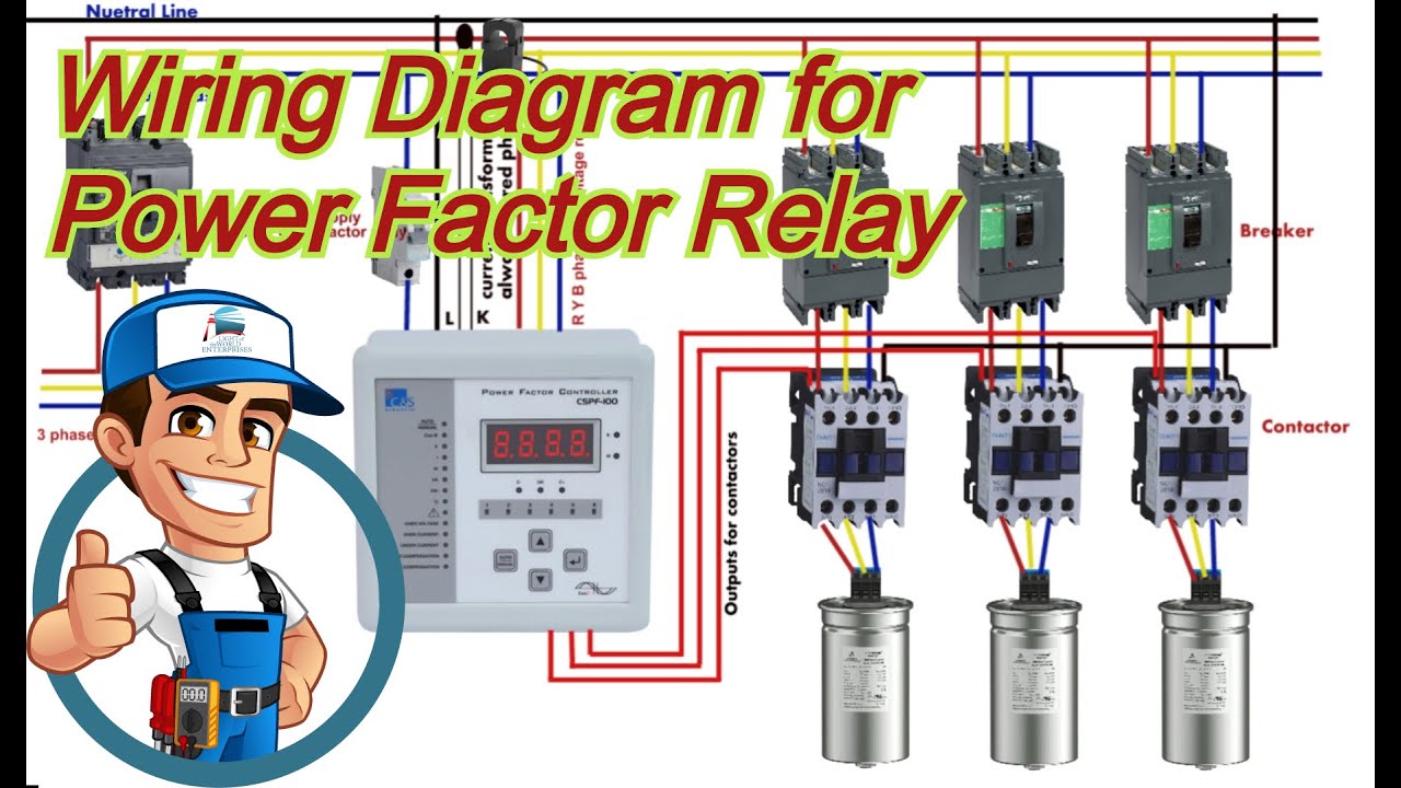
Wiring Diagram of Power factor correction relay - YouTube

Patent EP1944856A1 - A power factor correction circuit - Google Patents

Power Factor Correction A Short Story - thomashauer.at

Power Factor Wiring Diagram | PFI Wiring Diagram | Power Factor wire

Minor project for Electrical Engineering l l Automatic Power Factor