Boost Inverter Circuit Diagram
12v boost regulator circuit. Inverter 12v circuit diagram 220v dc ac transformer make making 220 electronic electronics board diy power transformers volt choose components Inverter 12vdc
Control block diagrams for (a) voltage source inverter (b) boost
Grant trebbin: how can current flow backwards through the inductor of a Dc/ac boost inverter block diagram Boost converters
Converter boost power circuit high diagram gadgetronicx step circuits voltage diy
Circuit inverter transformerless 150va boost ic 12v 220v using 500va 100va 200va 400va ampsBoost converter simple voltage conduction circuit dc diagram topology converters mode output discontinuous advantages schematic buck low analysis equilibrium articles 12 volt 1000 watt power inverter design processBoost converter circuit buck basic electronics pwm solar working battery mppt controller applications dc voltage high theory output fet control.
Voltage booster circuitBasic principle of the boost dc-ac inverter 150w boost converter schematicInverter principle.
Boost photovoltaic
Inverter diagram converter rv circuit wiring 1000w dc schematic board voltage boost power 1000 volt process watt inspirational circuits 12vDc/ac boost inverter block diagram Boost inverterJ 12 v 7 a 12 v 7.5ah s b de r €5.06 la-philosophie.com.
Circuit booster voltage components requiredPin on 12 volt to 220 volt inverter circuit diagram Boost inverter cascaded mpptCircuit topology for a two stage boost inverter.

Experimental diagram of dual boost inverter.
10+ boost converter circuit diagramHigh power boost converter circuit diagram Use a boost regulator beyond its rated voltageDc-dc-ac inverter boost.
How to build a dc-to-dc boost converter circuitControl block diagrams for (a) voltage source inverter (b) boost 1: boost converter and single phase inverter.Converter xl6009 coilgun.

Experimental diagram of dual boost inverter.
Inverter 20khz 220vac 12vdcBoost converter circuit with dc supply. Circuit diagram of boost to boost cascaded inverter system without mpptBoost current converter schematic inductor backwards flow through.
Inverter boostBoost converter circuit free download programs Circuit diagram: 1500w inverter full schematics and pcbInverter three.

Converter inductor breadboard
Circuit converter boost basic switching diagram seekic depends transistor transformer energy single storageInverter boost Schematic circuit of boost inverterDc to dc boost converter circuit diagram using mc34063 electronics.
Cascaded mpptInverter topology circuit Dc circuit converter boost diagram voltage variable charger choose board regulator power schematics batteryInverter circuit 500va,400va,200va,150va,100va,transformerless inverter.
.png)
Circuit diagram of boost to boost cascaded inverter system without mppt
Circuit regulator boost 12v voltage output diagram current volt 5v amp capacitor source circuits electronic varying unity gain buffer downDiscontinuous conduction mode of simple converters Boost converter circuit fig. 3 inverter circuit(a) single-phase boost inverter block diagram and (b) three-phase boost.
Circuit transistor bc337 voltage booster type suitable seem replacement boost stackInverter schematics pcb 1500w Boost diagram its regulator voltage rated beyond use converter ic analog devices block courtesy architecture shows figure.


Inverter 12VDC - 220VAC, 20kHz - EasyEDA

12 Volt 1000 Watt Power Inverter Design Process | GoHz.com
CIRCUIT DIAGRAM: 1500W INVERTER full schematics and pcb

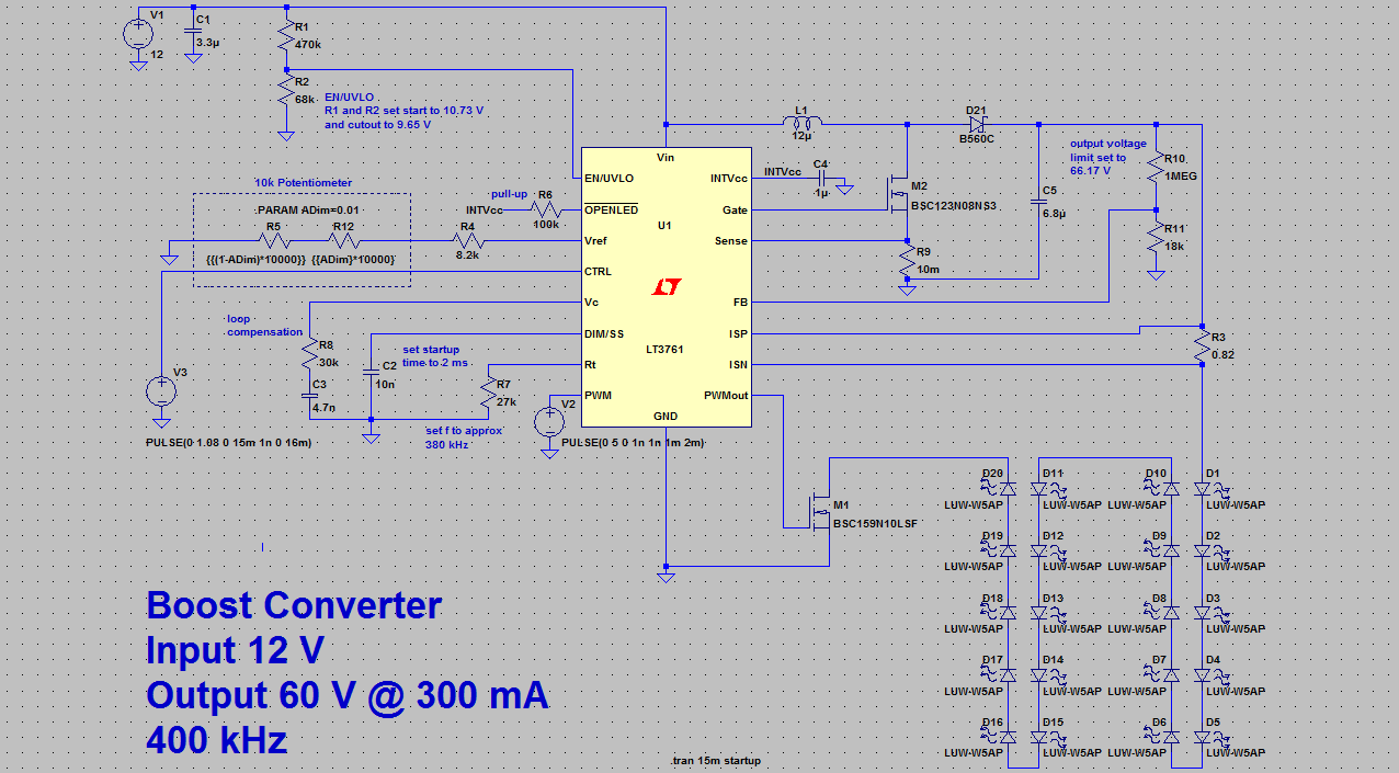
How to Build a DC-to-DC Boost Converter Circuit

Control block diagrams for (a) voltage source inverter (b) boost

Boost converter circuit Fig. 3 Inverter circuit | Download Scientific