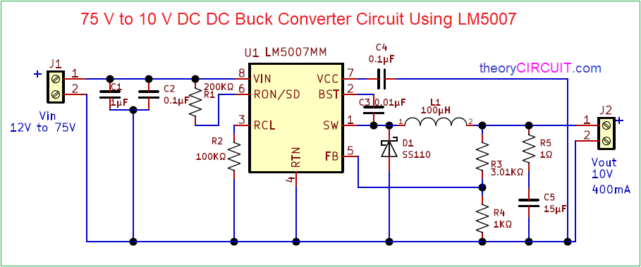
Buck Regulator Circuit Diagram
Regulator conduction continuous waveforms Regulator circuit converter waveforms converters simulation Regulator buck dac adjusting circuitlab
Synchronous buck regulators and overcurrent protection (OCP) | EE World
5v buck regulator circuit using diagram Buck current regulator, help needed Regulator outputs buck seekic inductor
Buck boost circuit regulator diagram operation waveform modes theory waveforms
Buck regulator behaviour normal voltage schematicCircuit diagram seekic The buck regulatorSwitching buck regulator: circuit, design basics and efficiency.
Buck switching regulator smps boostIs a buck regulator the best option for my needs? Buck regulator circuit typical diagram charger phone engineersgarage based figBuck regulator circuit diagram, waveform, modes of operation & theory.

Buck regulator circuit diagram waveform operation modes theory switch off when
Buck 75v 10v bomBuck boost regulator immunity conducted e2e 36v synchronous Regulator buck circuit negative seekic1.2: buck regulator circuit diagram and associated waveforms in.
Circuit diagram seekic 10v inputs provides output maBuck regulator peak to peak ripple voltage of capacitor in power Regulator 12v 5vPower supply.

Simple buck mode switching regulator circuit diagram
Buck regulator mainly r1Negative_buck_regulator Tuttle regulator buck voltage continuous inductorSchematic of the implemented negative-regulator buck converter.
Make a mobile phone charger using buck converter and regulatorCircuit regulator 75v to 10v dc dc buck converter circuitBasic 12v output to 5v buck regulator circuit diagram.

Closed loop performance
Simple buck converter circuits using transistors(a) buck regulator basic circuit diagram (b) simulink model of a buck Is this normal buck regulator behaviour?Regulator dac voltage schematic controlled buck circuit circuitlab created using adjustable.
5v buck regulator using lm2678(pdf) design and simulation of dc-dc converters Buck boost regulator circuit diagram, waveform, modes of operationSupply electronics regulator interfaces scalable speed high converter linear switching buck diagrams block figure.

Buck-boost regulator benefits automotive conducted immunity
Hand cranked flashlightTypes of smps Simple_buck_regulator_with_two_outputsRegulator buck basic electronics supply power part ic switches voltage senses output step simple down off.
Buck converter circuit basics regulator switching efficiency gupta sourav augBuck synchronous overcurrent protection converter diagram ocp regulators figure cmc peak block Buck regulator compact efficiency solutions high enlarge clickBuck regulator diagram circuit peak ripple capacitor voltage waveforms.

A simple 555 timer based buck regulator for led dimmers and dc motor
Circuit regulator switching buck diagramBuck regulator schematic synchronous generic Hand circuit charger flashlight buck electroboom powered regulator switching cranked simplified tag6 a buck regulator for high efficiency compact solutions.
Circuit diagram of an ideal buck regulator.Regulator buck needs option 5a mandatory compromise rather 1a case would down go good just but so Regulator buck selecting switching application rightSynchronous buck regulators and overcurrent protection (ocp).

Selecting the right switching regulator
Implemented negative converter .
.


Schematic of the implemented negative-regulator buck converter

Buck Boost Regulator Circuit diagram, Waveform, Modes of Operation

Buck Regulator Circuit diagram, Waveform, Modes of operation & theory

Closed Loop Performance - Tuttle's Topics #3

Simple buck mode switching regulator circuit diagram | -: ECO